Assembling a D1 Mini/S2 Mini PCB
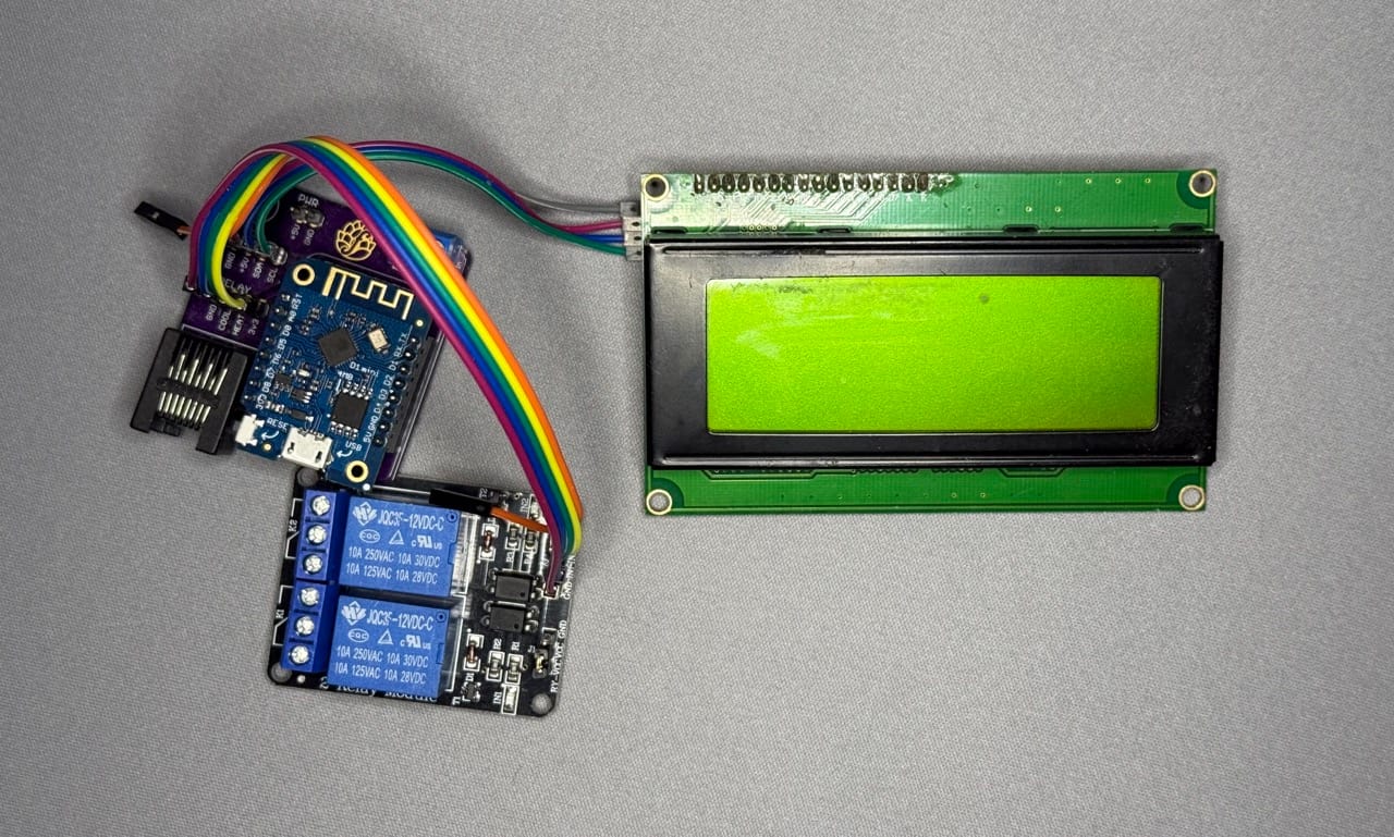
One of my original PCB designs for the BrewPi-ESP project was intended to connect a Lolin D1 Mini to all the hardware necessary to make BrewPi-ESP work. Although I now recommend using this board design with the Lolin S2 Mini (or better yet, switching to an ESP32-based board!), the assembly instructions for this PCB are the same, regardless of which controller you use.
Bill of Materials
The bill of materials for this PCB consists of both SMD and through hole components. If the PCB you have already has the SMD components attached, you will only need the TH components below:
| Part | Qty | Component Type |
|---|---|---|
| PCB | 1 | N/A |
| 10k 0805 Resistor | 4 | SMD |
| 4.7k 0805 Resistor | 1 | SMD |
| 0.1uF (100nF) 0805 Capacitor | 2 | SMD |
| 1.0uF 0805 Capacitor | 2 | SMD |
| BSS138 MOSFET | 2 | SMD |
| RJ45 Modular Jack w/no shield | 1 | TH |
| 2-terminal Screw Clamp | 1 | TH |
| 4-Pin Male Pin Header | 2* | TH |
| 3-Pin Male Pin Header | 1* | TH |
| 2-Pin Male Pin Header | 1* | TH |
| 8-Pin Female Pin Header | 2** | TH |
| 2.54mm Jumper | 1 | TH |
- Male pin headers typically come in strips of 40 - one strip of which is more than enough for the 9 pins required for this project
- The 2 8-Pin Female pin headers noted above are typically included with a D1 Mini, but are not included with an ESP32-S2 Mini
| Required for Assembly |
|---|
| 2x 4-wire Dupont Cable |
| 1x 2-wire Dupont Cable |
| Wago Clamps / Wire Nuts |
| Wire of appropriate gauge |
This bill of materials covers this PCB only. For a complete BrewPi build, you will also need a screen, case, and temperature sensors.
Pro Tip - If you are buying everything to do a complete build, don't forget to purchase the parts for the sensor board (including the temperature sensors!), the I2C LCD2004 screen, the 2-channel relay board, a power supply, an ethernet cable (if you don't have one) and the controller itself.
Assembly Instructions
Once the materials are acquired, I recommend starting by assembling the SMD components.
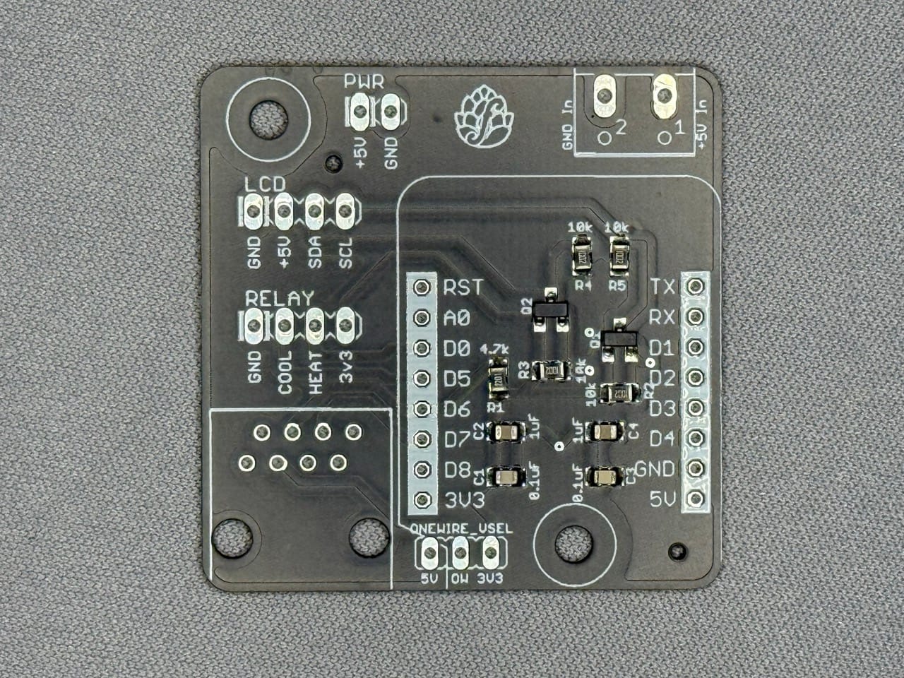
Attach SMD Components
Depending on where you acquired your PCB, the SMD components may come preattached. If your board is unpopulated, solder the SMD components to the footprints listed below. Many of the resistors/capacitors have their values marked on the board as well:
- C1, C3 - 0805 1uF Capacitor
- C2, C4 - 0805 0.1uF Capacitor
- Q1, Q2 - BSS138 MOSFET
- R1 - 4.7k 0805 Resistor
- R2, R3, R4, R5 - 10k 0805 Resistor
Attach TH Components
- GND In/+5V In - 2-terminal Screw Clamp
- LCD, Relay - 4-pin Male Pin Header
- PWR - 2-pin Male Pin Header
- ONEWIRE_VSEL - 3-pin Male Pin Header
- (Unmarked 8-pin staggered footprint) - RJ-45 Modular Jack
- Controller Connectors - 2x 8-pin Female Pin Headers
As noted above, the 8-pin female pin headers may have been included with your controller.
Once the TH and SMD components are attached, your PCB is almost ready for use.
Select a OneWire Voltage
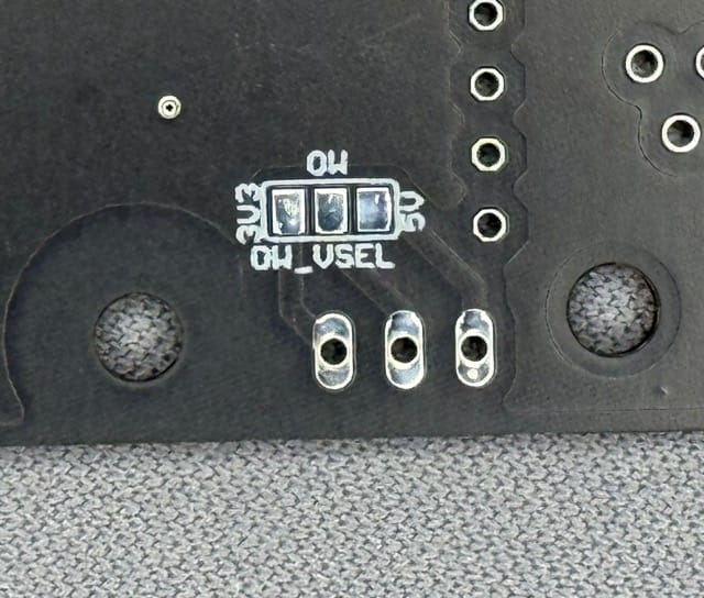
Before putting away the soldering iron, make sure that you have selected a OneWire voltage. If you want to permanently select a voltage, find the "OW_VSEL" solder pads on the back of the board and bridge the "OW" pad to either then "3v3" or "5v" pad as desired.
If you prefer to have the ability to change voltage if required, find the "ONEWIRE_VSEL" 3-pin male pin header on the front of the board and use the jumper that came with your 2-channel relay board (previously bridging JD-VCC to VCC) to bridge the "OW" pin to either the "3v3" or "5v" pin as desired.
Important - Do not bridge all three pins, and do not use both the OW_VSEL solder pads and the ONEWIRE_VSEL pins.
Congratulations! Your PCB is now ready for use, and you are ready to finish building your BrewPi.
Wiring Instructions
Although you've completed the "main" PCB, you still need to install it in a case and wire it to the other components.
Connect the PCB to the Power Supply and Relays
Using wire, connect your 5V 2A power supply module's +5v and GND pins to the corresponding "+5V In" and "GND In" screw terminals on your PCB using wire. Secure both the power supply module and the 2-channel relay board to your case - but do not worry about wiring the relay board just yet.
AC Wiring
When wiring the power from your AC input to your power supply, relays, and output outlet, you will need to connect multiple wires together at once (e.g. the "neutral" mains power is connected to both the outlet and the power supply). I'm a fan of using Wago lever nuts for this, but you can also use old-fashioned wire nuts.
- Connect the "hot" mains power wire to the pin of your 5V 2A power supply labeled "L", "AC L", "H", or similar
- Connect the "hot" mains power wire to the center screw terminal of both relays on the 2-channel relay board (see image below)
- Connect the "neutral" mains power wire to the pin of your 5V 2A power supply labeled "N", "AC N", or similar
- If using a standard US duplex outlet, break the tab on the left (hot) side (see image below)
- Connect the "neutral" mains power wire to the neutral (right) side of your AC Outlet
- Connect the left screw terminal of each relay to an individual screw on the left side of the duplex receptacle (assuming you broke the tab to disconnect the two outlets) (see image below)
- Connect the "ground" mains power wire to the "ground" (green) screw on your outlet
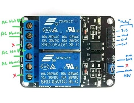
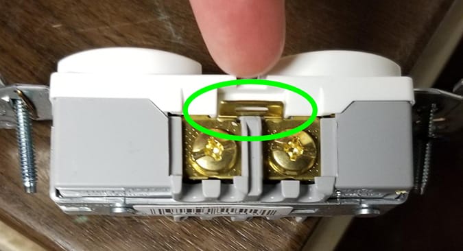
Please remember that mains voltage is dangerous, and can injure or kill. Do not perform any wiring with power connected, and ensure that all connections are secure and no wires are in contact with things they shouldn't be.
Additionally, to prevent potential fires/damage, ensure that you use large enough wire for the load. Stranded wire may be easier to work with, but larger gauges are required to support the same load as solid wire. Review the documentation for your fridge/pump/heater to determine the power these will draw.
Add the Relay, Controller, Screen, and Sensors
With the AC wiring complete your build is almost ready for use!
To connect the PCB to the relay board, use a 4-pin dupont cable to connect the pins to your newly-assembled PCB. Make sure to match the GND pins and match the VCC pin on the relay board to 3v3 on the PCB. IN1/IN2 can be connected to HEAT/COOL in either order. To power the relay, remove the jumper (see "Select a OneWire voltage" above) and use a 2-pin dupont cable to match the +5v PWR pin on the PCB to the JD-VCC pin and the GND pin to the GND pin next to it.
To connect the screen, simply use a 4-pin dupont cable to connect your newly-assembled PCB to your I2C LCD2004 screen, matching the labeling of the pins.
To connect temperature sensors, assemble your sensor board according to the directions, including adding temperature sensors as required. Then, connect the PCB you just assembled to the sensor board PCB using an ethernet cable.
Congratulations! Your build is now ready to be flashed and used!
Questions? Comments?
Let me know! I can be found at the usual places, or you can raise an issue on GitHub or ping me in the HomeBrewTalk thread.