New All-in-One BrewPi-ESP PCB Design

Throughout the life of the BrewPi-ESP project, the "base" build has required a minimum of four distinct components:
- An ESP-8266/ESP-32 controller
- A 2-channel relay board
- A 5V power supply
- A custom PCB to connect everything
While these components are relatively easy to source individually, having four separate parts introduces complexity, especially when it comes to wiring—whether you're assembling a complete build or just setting up a desktop test rig.
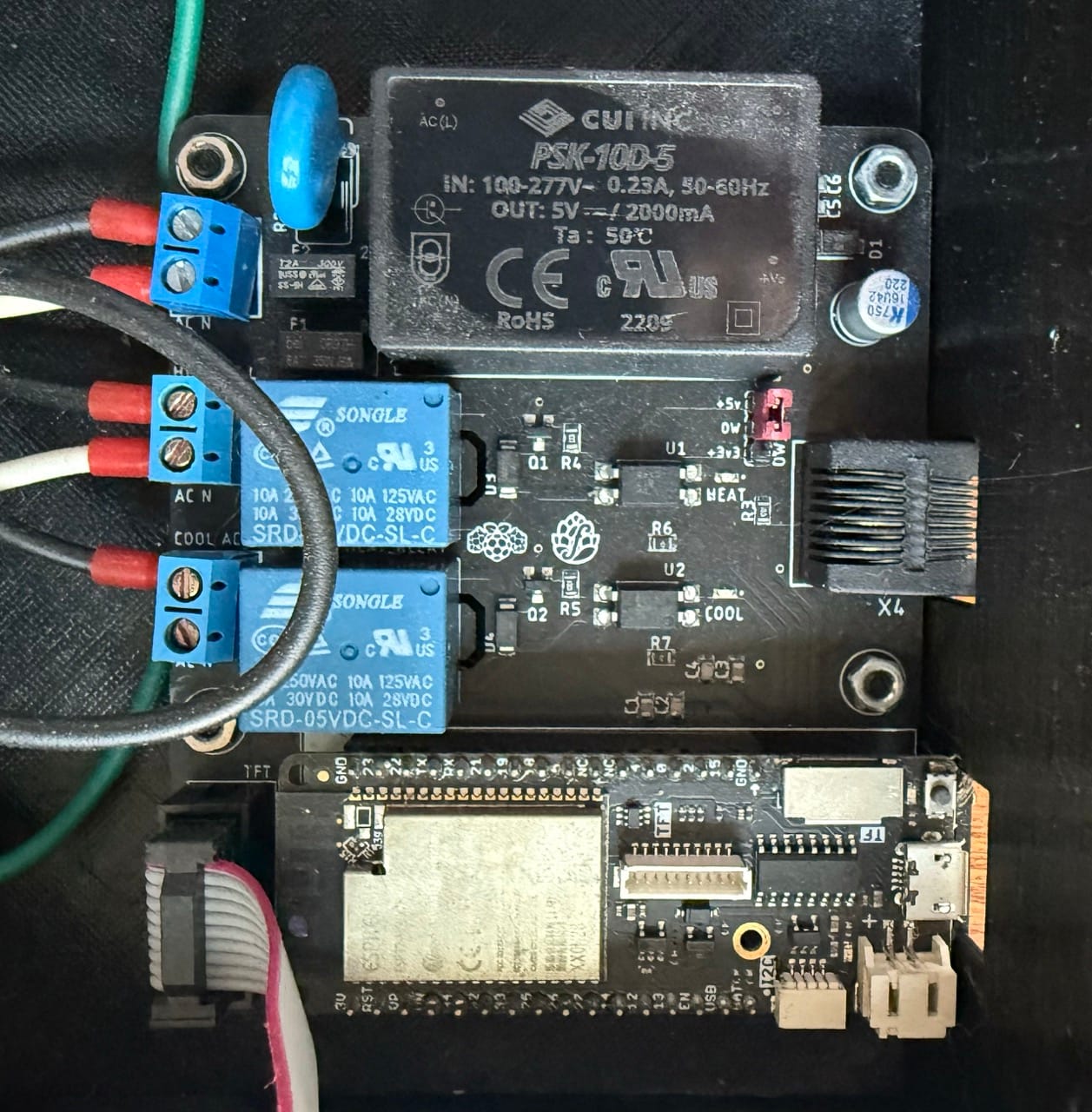
To simplify this, I designed a true "all-in-one" PCB that consolidates the majority of these components into a single board. Key features of this new design include:
- Integrated Relays: The board includes two relays for heating and cooling, removing the need for a separate 2-channel relay board
- Built-in Power Supply: A 5V 2A power supply is integrated directly into the PCB, eliminating the need for an external power module
- TFT Breakout Header: The design incorporates a breakout header for larger LCD screens, enhancing its flexibility for more advanced builds
- Enhanced Protection: Fuses and varistors are included to provide additional safety and protection for the components
- Simplified Wiring: By consolidating these components, the board significantly reduces the amount of wiring required

While I believe this new design offers significant benefits, it’s not without its trade-offs. Here are some considerations to keep in mind:
Advantages
- Streamlined Assembly: With fewer individual components, the build process is faster and less error-prone
- Compact and Tidy Setup: The all-in-one design results in a cleaner, more organized build
- Reduced Wiring: Single PCB design eliminates dupont cables and additional AC wiring
Disadvantages
- Larger PCB Size: The integrated design results in a larger PCB, which may increase fabrication costs at some manufacturers
- Reduced Modularity: If a component like the power supply or a relay fails, the entire board may need to be replaced or repaired
- Power (Current) Limitations: This board is not suitable for higher-amperage loads, which may limit its application in some setups
While this board might not be ideal for every use case, I believe it opens up new possibilities and makes the BrewPi-ESP project more accessible to a broader audience. I’m excited to release it and look forward to seeing how the community uses it in their builds.
Interested?
There are two designs for this (so far) depending on the power supply module in use. All designs are available on GitHub to be downloaded and sent to your fab house of choice. If I have PCBs left over from testing, I also tend to sell them on Tindie.
PSK-10D-5 - [PCB on GitHub] - [Buy on Tindie]
IRM-10-5 [Currently untested!] - [PCB on GitHub] - [Coming soon to Tindie once I get my test boards]
The PSK-10D-5 power supply is the original module I designed around, but appears to have since been discontinued by the manufacturer. The IRM-10-5 has a slightly different footprint, requiring a modified board design.
Assembly Instructions
The full bill of materials is available in the GitHub link above for the respective boards. Once acquired, I recommend starting by assembling the SMD components.
Attach SMD Components
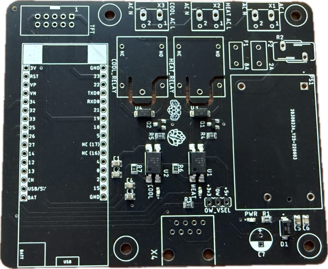
Depending on where you acquired your PCB, the SMD components may come preattached. If your board is unpopulated, solder the SMD components to the footprints listed below:
- C1, C3, C5 - 0805 1uF Capacitor
- C2, C4, C6 - 0805 0.1uF Capacitor
- COOL, HEAT, PWR - Red 0603 LED
- U1, U2 - Optoisolator
- D1 - SMAJ7.0A TVS Diode
- D3, D4 - 1kV DO-214AC Diode
- Q1, Q2 - NPN Transistor
- R1 - 680R 0805 Resistor
- R3 - 4.7k 0805 Resistor
- R4, R5 - 1k 0805 Resistor
Attach TH Components
Please attach the through hole components to their respective footprints listed below:
- X1, X2, X3 - 2-terminal Screw Clamp
- X4 - RJ-45 Modular Jack
- F1 - 8A Fuse
- F2 - 2A Fuse
- R2 - Varistor
- C7 - 220uF Aluminum Capacitor – See note below about polarity
- HEAT_RELAY, COOL_RELAY - Songle 5v Relay
- OW_SEL - 3-pin Male Pin Header (and jumper)
- TFT - 10-pin Box Header (take note of the side with the "notch" and align to the white box silkscreened to the PCB)
- Controller Connectors - 2x 16-pin Female Pin Headers
You will also need to solder the power supply appropriate for your board to your PCB in the appropriate location
Important - Be careful of the polarity of the 220uF Aluminum Capacitor. The anode (positive lead) is the longer one, and is marked with a + on the PCB. The cathode (negative lead) is typically on the "shaded" side of the capacitor or has a polarity band marking.
Select a OneWire Voltage
Before putting away the solder iron, make sure that you have selected a OneWire voltage. If you want to permanently select a voltage, find the "SJ_OW" solder pads on the back of the board and bridge the "OW" pad to either then "+3v3" or "+5v" pad as desired.
If you prefer to have the ability to change voltage if required, find the "OW_SEL" 3-pin male pin header on the front of the board and use a jumper to bridge the "OW" pin to either the "+3v3" or "+5v" pin as desired.
Important - Do not bridge all three pins, and do not use both the SJ_OW solder pads and the OW_SEL pins.
Add the Controller, Screen, and Sensors
This PCB integrates the power supply and relays, but still relies on a separate D32 Pro microcontroller, BrewPi-ESP Sensor Board, and screen.
Wiring Instructions
Due to the "all-in-one" nature of this PCB, wiring is extremely straightforward relative to other builds.
- Connect the "hot" or "live" wire of your AC Input to "AC L"
- Connect the "neutral" wire of your AC Input to "AC N"
- Wire the "HEAT AC L" and corresponding "AC N" screw terminals to the appropriate pads on your outlet
- Wire the "COOL AC L" and corresponding "AC N" screw terminals to the appropriate pads on your outlet
Although I live in the US and test with 110v, this PCB is compatible with 220v-based builds as well.
Questions? Comments?
Let me know! I can be found at the usual places, or you can raise an issue on GitHub or ping me in the HomeBrewTalk thread.